Welcome to the official website of Shenzhen Kaidexun Technology Co., Ltd.
-
 contact number
15013429139
-
 Email address
 -
 office hours
Mon-Sat:9.00am to 18.00pm
Welcome to the official website of Shenzhen Kaidexun Technology Co., Ltd.
15013429139
Mon-Sat:9.00am to 18.00pm
Shenzhen Kaidexun Technology Co., Ltd.
Fixed line: 0755-28198006
Mobile: 15013429139
Fax: 0755-28169083
Mail: zhao.jh@kaidexun.com
Address: 2nd Floor, Building 18, Jiuwo Longjun Industrial Zone, Heping West Road, Dalang Street, Longhua New District, Shenzhen
after sales support
Fixed line: 0755-28198006
Mobile: 13823555655
Complaints and suggestions: 13823555655

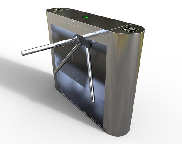
How to install the intelligent tripod gate, generally determine the installation location of the main gate of the gate according to the left and right direction of the selected gate and the actual situation on the installation site. For the non-concrete foundation or the main slope of the gate is installed with slope, it is recommended to lay concrete foundation...
Send InquiryChat NowHow to install the intelligent three-roller gate, generally determine the installation position of the main gate of the gate according to the left and right direction of the gate and the actual situation on the installation site. For the case where non-concrete foundation or main road gate is installed with slope, it is recommended to lay concrete foundation, and ensure that the foundation and foundation are firmly combined, and the verticality of the main body of the three stick gate and the horizontal plane is less than 1°.
The three-roller gate installation process steps are as follows:
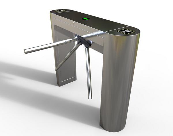
(1) Line embedding: the location of the chassis is determined according to the requirements of the customer. If you need to cast a concrete base, you can complete it in advance (the size of the base is about 100-150mm more than the outer size of the bottom of the barrier), at the fixed position of the chassis Pre-buried or excavated cable trenches from the center point of the control room or the police box, buried the wire tube, penetrated the 2X1.5 square millimeter power supply line and 4X0.5 square millimeter control line used by the equipment, after confirming that it was correct, backfill concrete .
(2) Fixing the chassis: Put the three-roller shutter chassis in a fixed position, open the chassis door, and loosen the butterfly nut that fixes the cap (put the chassis door and cap on carefully to avoid scratching the surface). Then mark the center of the screw holes of the chassis bottom and the edge of the chassis base, remove the gate, and drill holes vertically with a drill bit (the size of the drill bit should match the expansion bolts provided with the equipment), The depth should meet the length requirement of the expansion screw. Move the chassis to its original position, drive in the expansion screws and fasten them firmly.
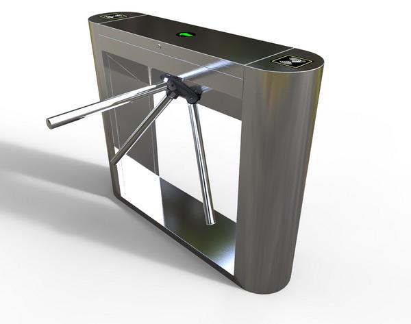
(3) Installation of the brake lever: After the tripod brake chassis is firmly fixed, the brake lever can be installed at the position of the lever, tightened with the provided screws, and make sure that the brake lever is not inclined. If you need to install the fork rod, after debugging the vertical and horizontal state, shake the brake rod to the horizontal position by hand, determine the installation position of the fork rod at the end of the brake rod, and fix the fork rod firmly with screws (no installation is required without the fork rod) ).(4) Peripheral equipment installation: After the three stick gate is installed firmly, and after the debugging is completed, according to the needs of the customer, according to the wiring diagram of the gate control board, connect the chassis circuit and the control circuit of the relevant peripheral equipment, and carry out the relevant debugging
One. Features
1. It has a clear traffic direction indication function, with an intuitive arrow indicating whether it can pass (need to connect a direction light board).
2. With anti-trailing function: when passing each time, it will automatically cancel the passing time to prevent personnel from anti-trailing.
3. There are a variety of working modes to choose from, that is, one-way traffic, two-way traffic, and the signal to open the main board
(Need to connect another control system. Access control. Fingerprint, etc.) Control access, etc., can be set through the motherboard menu.
4. With automatic reset function: when the passer-by signal is received and the passer does not pass within the specified time, the system will automatically cancel the passer's current access authority, and the limited pass time can be set in the main menu set.
5. It has the function of power off and falling rod to meet the special needs of users and fire safety requirements.
6. The working mode of the direction electromagnet and limit switch can be adjusted to meet the needs of different customers.The working mode of magnet and limit can be used for high-turn brake).
two. Function Description
1. There are six buttons on the motherboard. The two buttons S4 and S5 in the lower left corner of the motherboard are the left and right gate buttons respectively.The S1 menu key in the lower left corner of the screen is used to enter and exit the menu or; S2.S3 are the up and down keys for menu item selectionSelect and add or subtract the parameters to be set.
2. The display screen refers to the 3-digit LED digital tube displayed from left to right on the main board; it is 000 during normal operation.
3. Enter the menu: press the menu key, then the display shows "P00", indicating that you have entered; exit the menu statusAt this time, you can use the up and down keys to select the function number of the set function; press the up key, the function number plus
1. Press the key to decrease the function number by 1; there are 5 function settings, namely:
P00: enter; exit the menu;
1. Gate type P01: 1- 0: The electromagnet is effective when it is energized (that is, the electric opening is applicable to the three-roller gate); 1-1. The direction electromagnet is effective when it is powered off (that is, the power is turned off; it can be used for high speed Gate) The default is 0;
2. System initialization P02: 2- 0; No 2-1; System initialization (restore the system default initial value)
3. Set transit time P03: 306 means the maximum time for each person to pass through the channel; the default is 6 seconds,
4. Gate working mode P04: 4-0; left and right controlled (swipe) 4-1; left controlled (swipe) and rightFree passage 4-2; the right side is controlled (swipe) and the left side free passage defaults to 0
5. Test function P05: 5-0; exit test 5-1; start gate test default to 0
6. Left counting and clearing P06: 6=0 count or not count (0 means no count, 1 means count)
7. Right counting and clearing P07: 7=0 count or not count (0 means no count, 1 means count) 6=1 view count 6=2 clear by default does not count
8. Memory function P08: 8-0 no memory 8-1 left memory 8-2 right memory 8-3 left and right memory default no memory function
9. Pass setting P09: 9-0 left and right pass 9-1 left pass is prohibited right 9-2 right pass is prohibited left 9-3 all
15013429139
2nd Floor, Building 18, Longjun Industrial Zone, No. 9, Heping West Road, Dalang Street, Longhua New District, Shenzhen City
zhao.jh@kaidexun.com

